[My apologies. I fumble-fingered WordPress and published a draft version of this article that was incomplete. This is the corrected version. ]
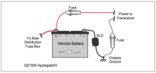
Sometime during the 20th Century, I learned that fuses (or circuit breakers) are used in electrical circuits to prevent catastrophic failure. Fuses open in response to an electrical fault that causes excessive current to flow. The job of the fuse is to minimize the damage and keep things from catching on fire. When I started installing amateur transceivers into vehicles, I learned that you should connect wires directly to the car battery (or darn close) and you should fuse both the positive and negative power leads. I was surprised by the need for two fuses, but there are technical arguments for it. Besides, the transceiver manufacturers recommend it in their manuals. (See figure below.)

I am focusing this discussion on a typical 2m/70cm FM transceiver installation – that is what I have the most experience with and that is the most common ham mobile installation. Such a radio typically draws ~10 A on transmit, so the DC power is usually fused with something like a 15 A (or 20 A) fuse. Keep in mind that a 15 A fuse is not going to protect delicate circuitry but might stop more serious damage or fire.
Connect To The Battery?
Alan/K0BG has an excellent website that provides guidance on mobile radio installations. He points out that modern vehicles usually have an Electrical Load Detector (ELD) inserted into the negative lead of the battery, so that the vehicle control systems can monitor the state of the battery. It is important to connect your radio on the “other side” of the ELD, near where it connects to the vehicle chassis. Oh, and never use the existing vehicle wiring to power your radio (especially not the 12 V accessory plug).
One Fuse or Two Controversy
Recently, I became aware of controversy with regard to proper fusing. Some people are questioning the practice of fusing both DC power leads, while others are vigorously defending it.
For example, there is a lively eham.net discussion here. Ed/W1RFI provides some useful insight on the ARRL forum. Alan/K0BG covers the topic of DC power on his wiring and grounding page. Tom/W8JI argues for the one fuse approach on his website.
What Do The Manufacturers Say?
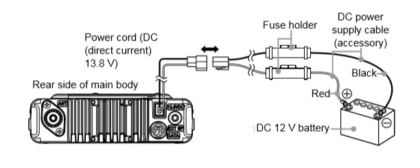
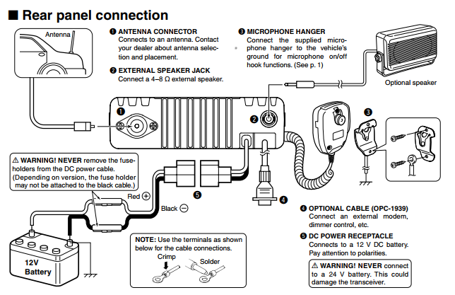
Generally, you should follow the advice of the manufacturer on any equipment installation, so I took a look at a few owner’s manuals. Most (or all?) of the manuals for the amateur gear show the two fuse method. See the ICOM example below. (Note that they don’t show the presence of the ELD.)
I also took a look at some commercial land mobile radio manuals. Motorola shows the single fuse approach.
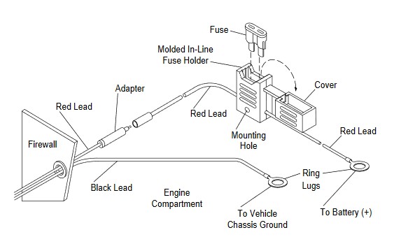
Hytera also shows a single fuse in its land mobile manuals.
ICOM makes both amateur and commercial land mobile gear, so I wondered what they recommend for their land mobile product line. Ha, funny thing, they show two fuses, with a comment that says, “Depending on version, the fuse holder may not be attached to the black cable.” Well, isn’t that special?
So is the two-fuse thing some kind of ancient amateur radio practice and the land mobile industry has gone a different path? Sometimes industries adopt “standard” approaches and then forget why with time.
Some Circuit Analysis
After reading through all of the arguments, I tried to distill them down to their essence. I created a wiring diagram that may help explain the concepts. Or maybe not. An automobile is a complex electrical and electronic system, so any practical diagram risks oversimplifying the situation. But here’s my best shot at it.
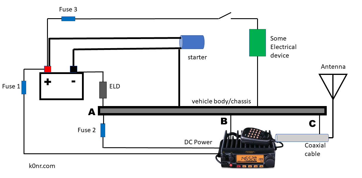
The center of the diagram shows the body/chassis of the vehicle which is connected to the negative lead of the battery, through the ELD. The transceiver is directly connected to the + terminal of the battery (via Fuse 1) and the chassis side of the ELD (via Fuse 2). The engine starter is connected to the battery with heavy cables and is also connected to the body/chassis. While there are a large number of other electrical devices in a modern vehicle, only one is shown here as an example (with a switch and fuse).
The circuit shows the antenna connected to the radio with a coaxial cable. The shield of that cable is almost always grounded to the vehicle chassis at the antenna. (Magnetic mount antennas are one exception and I am sure there are others. Update: Ron/N0IVN pointed out that the on-glass antennas are not grounded.) I can say that every mobile installation I’ve ever done had the coaxial cable connected to the chassis. This is an important point because it provides a chassis connection for the transceiver at point C (whether you wanted it or not). There may be other ways that a transceiver is connected to chassis (point B), including the mounting bracket, external speaker, microphone or other accessories.
Arguments For and Against
The argument for fusing the negative lead is to protect against return current from other devices that find its way back to the battery through the transceiver’s negative power lead. For example, the starter could have a fault in its negative cable, causing the current to flow through the chassis to the transceiver and back to the battery. The starter current can be hundreds of amperes which would likely overload the radio wire which is sized for 15 amperes. The fuse will open and protect the negative lead (and maybe the radio, to some extent).
The argument against fusing the negative lead is that if the fuse opens up, it could cause problems. Suppose Fuse 2 opens up due to some transient condition. If the transceiver is completely isolated, Fuse 2 would remove power from the transceiver. However, the return path at the antenna coax (point C) will most likely allow the radio to continue functioning using the coax as the negative return. Typically, this is RG-58 or similar cable, which is not intended to carry significant DC current and may fry under the load. If the current is coming from a fault in the starter wiring (big current), this is going to be a bad day for your mobile.
My Conclusions
I think both arguments have merit but choosing one fuse or two requires estimating which problem is most likely and judging the overall impact of the fault. The negative lead fuse can do only one thing well: protect the negative lead. It might provide some protection to the transceiver but there are a lot of sensitive circuits inside the radio that will get destroyed with 15 A flowing. Again, the connection at point C means that the radio will be connected to chassis and current can flow.
If Fuse 2 is eliminated it allows for the flow of high currents through the negative lead of the transceiver. This is not desirable but is it better or worse than the current flowing through the coax shield? Probably better. If a high current device (the starter) has a wiring failure that dumps large currents into the chassis, it may find a number of return paths. Lots of current is going to flow somewhere and potentially cause damage, with or without a negative lead fuse.
I will note that bonding the transceiver to the vehicle chassis has some benefit (point B in the diagram). You may or may not have this connection depending on how you mounted the radio. This electrical connection can shunt any currents away from the coaxial cable, hopefully doing less damage that way.
What am I going to do? My future mobile installations will have only one fuse in the positive lead. I’ll also bond the radio body to the vehicle chassis, with a hefty, low-resistance connection.
My existing mobile installations all have two fuses. I won’t be changing them out because the risk of inducing a problem with the negative lead fuse is rather low. I don’t see the negative lead fuse as a big risk. If you choose to follow the amateur radio manufacturer’s two fuse recommendation, I understand.
A Request
The amateur radio equipment manufacturers need to give this issue a fresh look. At a minimum, the presence of ELD’s needs to be addressed and the common recommendation of wiring directly to the battery is obsolete. But the one-fuse-or-two issue should also get a careful look by the manufacturer’s engineering teams.
That’s my analysis. What do you think?
(Runs and ducks for cover.)
Note: This article is my technical opinion but my attorney says to tell you that you are responsible if you destroy your vehicle while wiring up your transceiver.
Great article, Bob! Thanks for taking the time to post such good lessons.
I connect the positive lead to the starter solenoid hot side (my vehicle is a 96 ford Ranger) and the negative lead to a good chassis ground. If the radio has two fuses, I will use them.
While you are under the hood wiring the radio to the battery, inspect and, if necessary, replace the piece of braid that connects the car body to the engine block. It’s this piece of wire or braid that we’re worried about failing and burning up ground wiring. You might save a universal joint.
Excellent point, James.
Thanks for the thorough analysis. Though we’ve come to the same conclusion and only use a fuse on the positive side, you pointed out a failure mode I hadn’t though of. (and there’s *always* a failure mode that I haven’t though of…)
I have used 2M Ham radios in all my cars since becoming a HAM. The trouble with the quote in the article, “Oh, and never use the existing vehicle wiring to power your radio (especially not the 12 V accessory plug).” is almost impossible to achieve in many more modern vehicles without drilling holes through the firewall. To do this would mean drilling blind, not knowing for sure what is on the other side, AND without removing the dashboard to do it. The engine compartment in most family vehicles is so tight that to get a drill where you might risk drilling is not possible. Dilemma! Then there the cost of removing the dash or the engine to drill the hole, probably far more that the cost of replacing the radio — there are many that cost under $200 theses days. So, yes I have 2-Meter radios in both of my cars connected 10 W fused in series through the accessory port ( plug and vehicle fuse system). I take care to transmit no more that at 65W or less. If anyone knows a better way to connect the power leads direct to the battery through the firewall I would love to know.
Jonathan,
I have not had to drill a hole in an automobile firewall in many years. Modern vehicles have access holes provided…some of them are already in use, so you have to squeeze in additional power cables. Often, there are unused holes (with rubber plugs in them), intended for accessory equipment. These may not be obvious though…I check youtube and online forums for examples of people doing accessory installations (might be ham radio, might be CB, might be high-end audio…doesn’t matter). For example, take a look at my blog posting showing a Jeep Wrangler installation: https://www.k0nr.com/wordpress/2012/05/jeep-wrangler-radio-install-2/
Bob K0NR
Thanks. I’ll do some research on my vehicles